- Stationary system for detecting contact forces and vehicle masses
- Detection of wheel contact on tread
- System communication via fail-safe data
- Number of measurement axes not limited
- Flexible measuring bridge length
- Suitable for use on all rail types from S49 upwards, independent of gauge
- Flat design allows installation with minimal changes
- Dynamic measurement possible
- Calibration by accredited body
- The system has been developed in accordance with applicable regulations (DIN 27201, DIN EN 50215, EN 14363, etc.)
- Bridge number not restricted
- Operation with UIC and DIN-compliant software
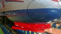
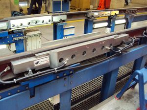 Every change to bogies results in a contact forces change.
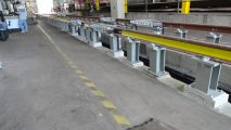
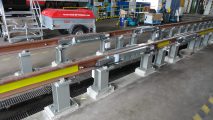
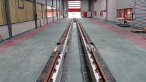
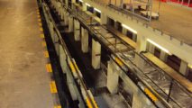
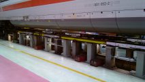
The SERAS stationär system not only serves to detect the wheel forces of track vehicles, but is also a wheel and axle load weighing system. The measurements in workshops can take place both statically and dynamically. The measuring system SERAS stationär is particularly suitable for the final inspection of vehicles in measuring tracks. Furthermore, adjustments can be made to the bogie directly on the system. Since the measurement data are sent via industry data radio to panel PCs, the changes in the measured values can be found directly on the bogie. This allows targeted work and therefore optimises workflows.
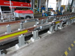
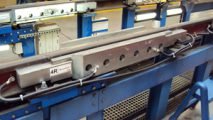
The sensing bars SERAS stationär are characterised by their extremely flat design. The space required for the measuring system corresponds to the height of the rail used. Accordingly, no changes need to be made to the substructure. For bumpless loading of the vehicles, the rail heads are provided with 45 degree cuts.
In this system, the wheel forces are determined on the tread.
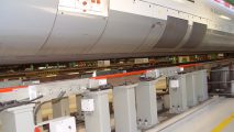
All metrological components are located left and right on the rail web and are directly integrated into the existing rail.
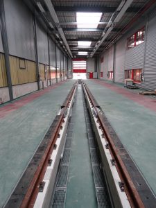
The rails are designed to bend to a maximum of 0.35 mm at full load (150 kN). This deflection is significantly lower than the one required by DIN for measuring tracks values. The measurement system accuracy is 0.3%.
The individual measurement bars are connected to one another via a data bus. This reduces the installation costs significantly. The data bus is connected to a control box, in which the industrial radio transmission device necessary for communication with the notebook (or panel PC) may also be located.
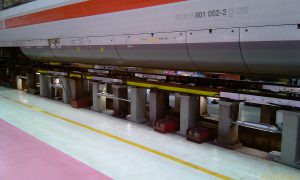
The measurement data analysis can be done on laptops, touch panel PCs or on radio data metrics displays. In the case of necessary adjustments on bogies, these devices can be taken directly to the vehicle where the corresponding adjustments to the bogie can be carried out. The changes made, including error calculations are displayed dynamically on the measurement surface vie the industry wireless data connection. Software installed on the computer is Sera Soft Touch-oriented, so that all inputs and measuring operations can also be performed via the touch screen. The individual measuring points can be optionally integrated into the measurement process.
The report generation and error calculation is performed according to the requirements of DIN 27201-5.
Technical data measuring system
| Allowable load capacity (axle load) | 30.000 kg – 40.000 kg |
|---|---|
| Rail profiles | All standard profiles from S49 upwards |
| Gauges | No restrictions |
| Protection class | IP 67 |
| Data transmission | Digital data bus |
| Computer connection | Industry data radio, USB, Ethernet |
| Supply voltage | 230V/50Hz |
| Number of measuring bridges used | Not limited |
Technical data measuring points
| Allowable load capacity (wheel load) | 15.000 kg – 20.000 kg |
|---|---|
| Measuring force per measurement point | 125kN - 150kN / 12.500 kg - 15.000 kg |
| Protection class | IP 67 |
| Division | 0,01 kN / 1 kg |
| display resolution | 20.000 |
| Accuracy class | (0,5) / (0,3) |
| Nominal temperature | -10°C to 65°C |
| Storage temperature | -40°C to 85°C |
